1. Technical Specifications
General specifications
| Charging Mode (IEC 61851-1) | Mode 3 |
| Dimensions without cable | 198x201x99 mm (without cable) |
| Weight without cable | 1.3 kg (without cable) |
| Operating temperature | -25 ºC to 50 ºC |
| Storage temperature | -40 ºC to 70 ºC |
| Environmental ratings | IP55, IK10 (High Resistance) |
| Installation site | Indoor and Outdoor use |
| Mounting type | Fixed equipment will be wall-mounted. Floor mounting with suitable Wallbox accessories. |
| Intended for use | Equipment intended for use by ordinary persons. |
| Location Access | Equipment for both unrestricted access locations and restricted access locations |
| Product conformity | RED Directive 2014/53/EU, RoHS Directive 2011/65/EU and BS 7671:2018+A1:2020+A2:2022 Compliant with UK Smart Charge Regulations |
Electrical specifications
| Charging power | 7.4 kW (1P) | 11 kW (3P) | 22 kW (3P) |
| Nominal voltage AC ± 10% | 230 V | 400 V | 400 V |
| Configurable current | from 6A to rated current |
| Nominal frequency | 50 Hz / 60 Hz |
| Nominal Diversity Factor (RDF) | 1 |
| Residual current detection | 6mA DC |
| Nominal insulation voltage | 400 V |
| Nominal impulse withstand voltage | 4000 V |
| Overvoltage category | CAT III |
| RCCB | Type A, B or EV may be required according to regional regulations |
| Protection against electric shock | Class I |
| Cable cross-section | Up to 13 mm² |
| EV power supply equipment connection | AEVCS permanently connected to AC mains |
| Pollution Degree | PD3 |
| Electromagnetic environment | Class A + Class B |
2. Safety Warnings

- Flying debris, risk of eye injury
- Risk of Electric Shock. Disconnect and wait 10 min
- Caution
- Sharp element, risk of cuts
- Earth connection required
- Special waste disposal
3. Tools and Mounting Parts
Required tools
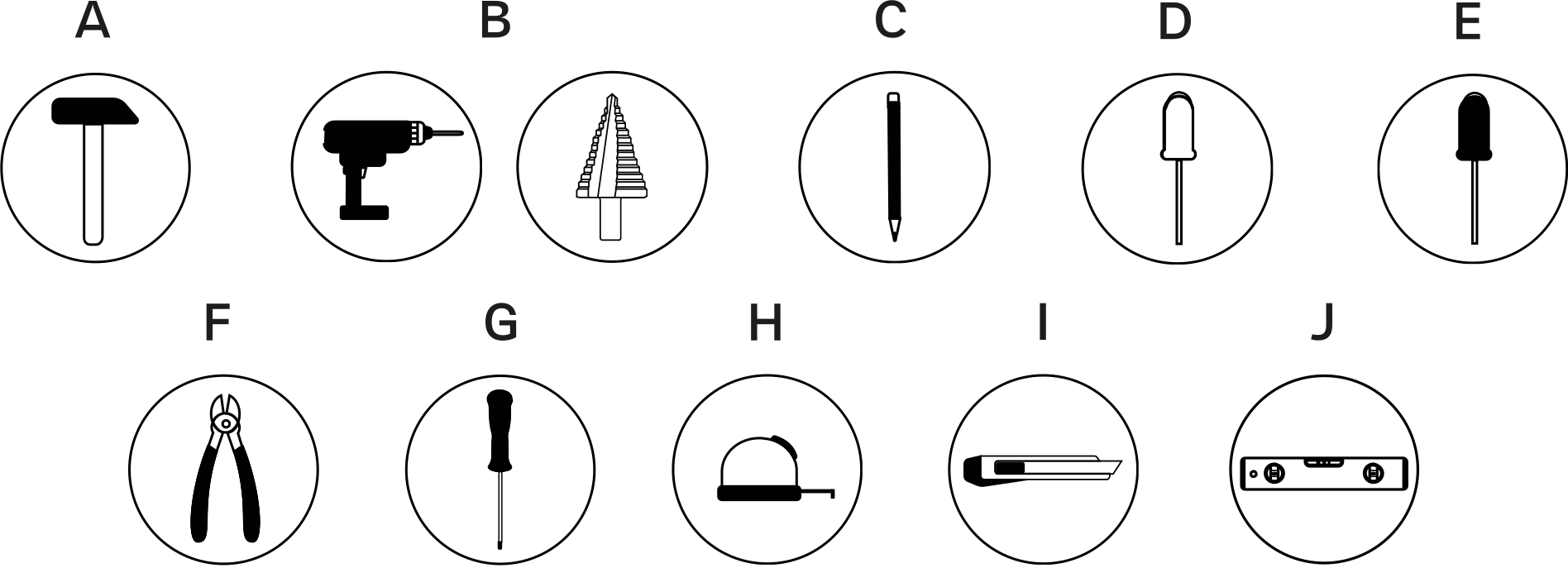
- Hammer
- Step drill 32mm and 8mm drill bit
- Pencil
- Flat screwdriver
- Phillips screwdriver
- Cutting pliers
- Torx T20 and T15
- Tape measure
- Utility knife
- Spirit level
Included mounting parts

- Phillips screws ø6 x 50 mm
- Phillips screws ø5 x 40 mm
- Wall anchors ø8 x 40 mm
- M32 gland
- Torx screws T20 4 x 10 mm
- Torx screws T15 ø3.5 x 8 mm
4. Preparing the charger
Remove the two corner screws and carefully lift the cover. Then, carefully disconnect the ribbon cable and set the cover aside.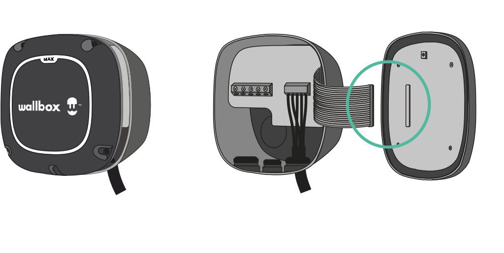
5. Installing the Wall Plate
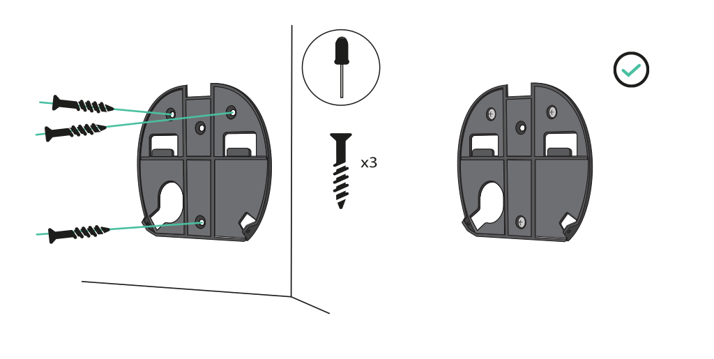
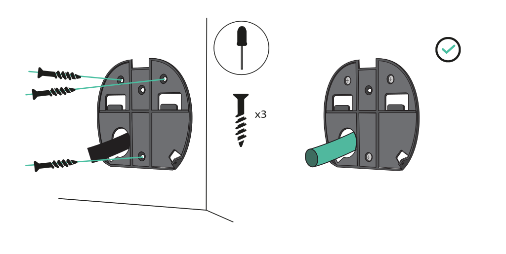
Remove the tape from the wall plate to detach it from the charger. Then, level it and mark three holes with a pencil. Now, with an appropriate size drill, drill and insert the wall plate aligned with the holes.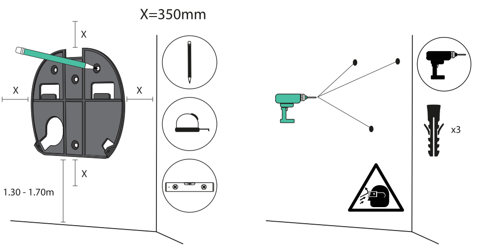
6. Lower Connection
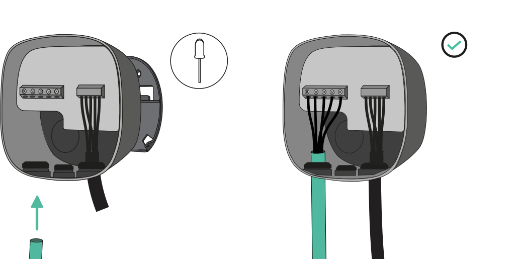
Both lower and rear connections are possible when installing Pulsar Max. If you want to install the product through the lower hole, you must follow the instructions below. For the rear connection, go to chapter 7. Lift your charger and hang it at the top of the wall plate. Secure the charger to the wall plate with the appropriate screws, do not overtighten them.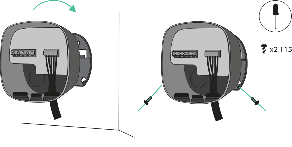
7. Rear Connection
Make a hole on the rear of the charger with a 32mm Step drill. Then, make an incision in the gland and insert the power supply cable.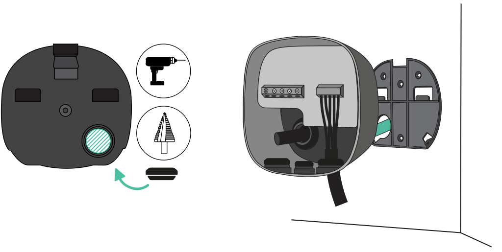
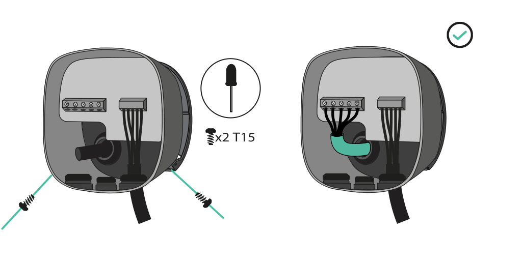
8. Electrical Wiring
Single-Phase Version
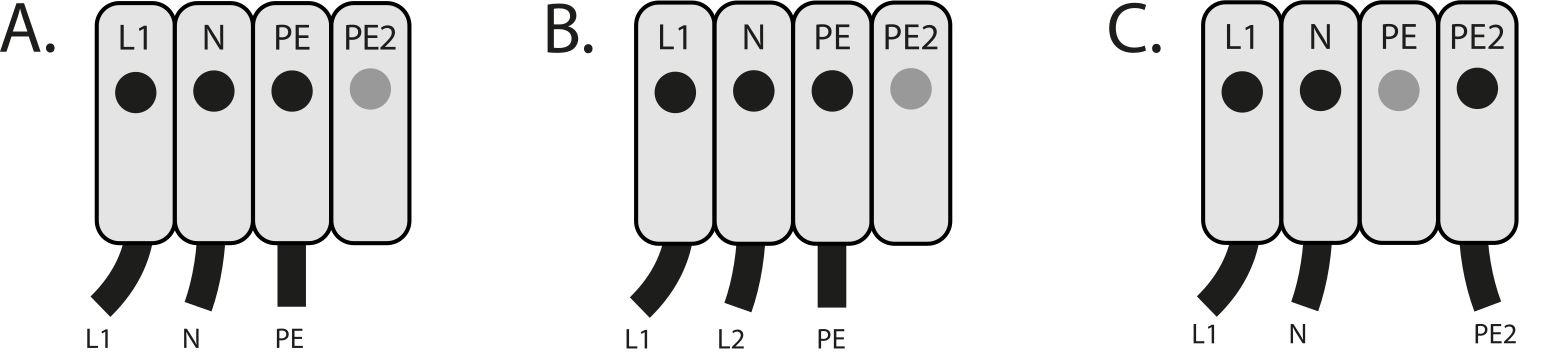
- Single-phase setup
- Bi-phase No Neutral
- Single-phase PME
Three-Phase Version
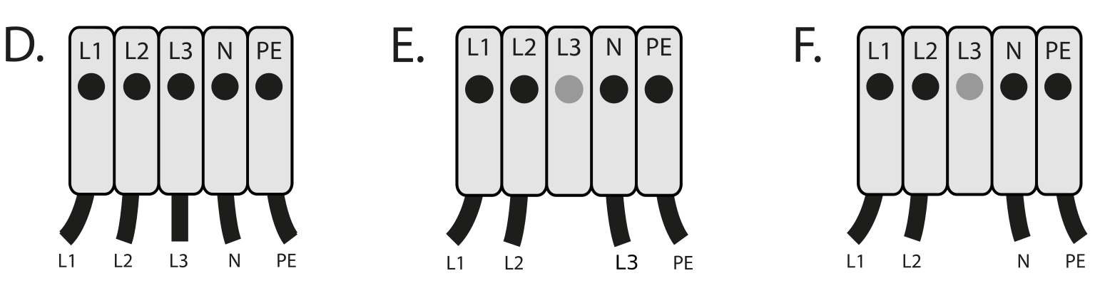
9. Closing the charger
Set the current selector to an appropriate setting. Then, carefully reattach the communications cable to the charger’s cover and close it. Ensure the selector is not pointing at 0, 8, and 9.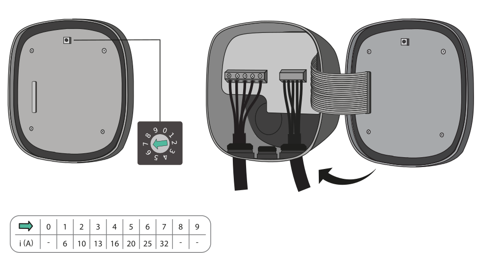
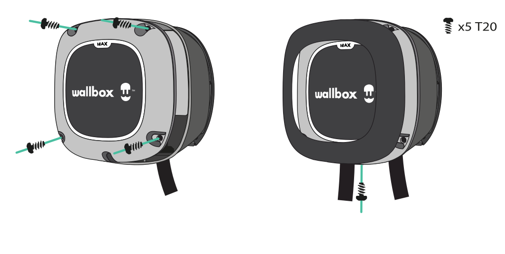
10. Installing the Plug Holder
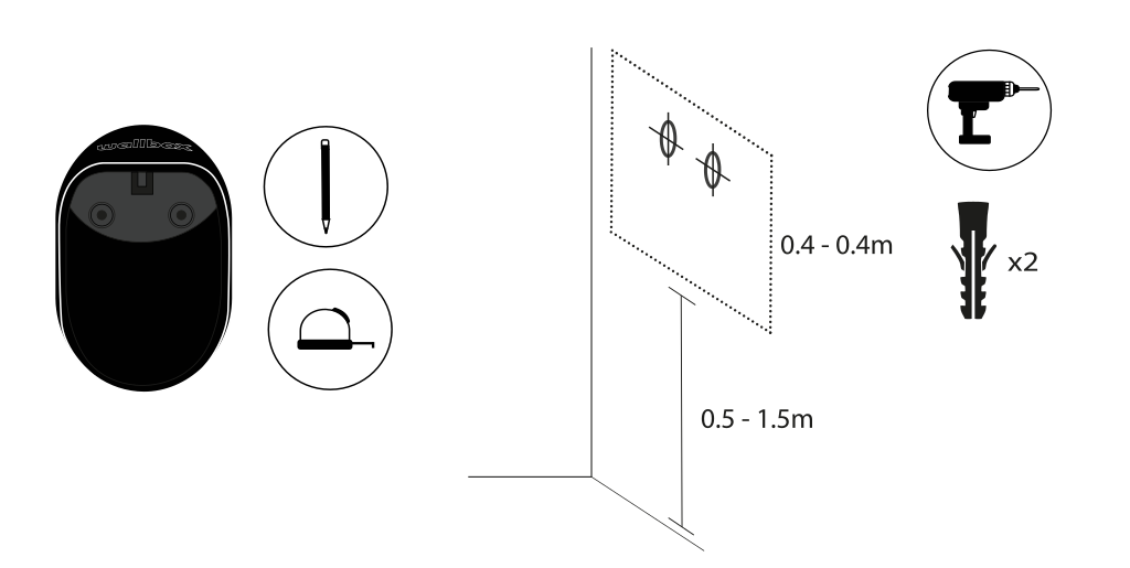
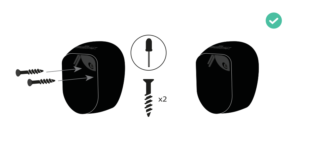
Place the plug holder on the wall and mark the fixing points. Then drill holes where the fixing points are marked.